Jeep Parts Wiki | Ford Parts Wiki
Home | Search | Browse | Marketplace | Messages | FAQ | Guest
|
Camaro Assembly Manual April 1968 |
|
Prev
 Next
Next
3940195
3940195
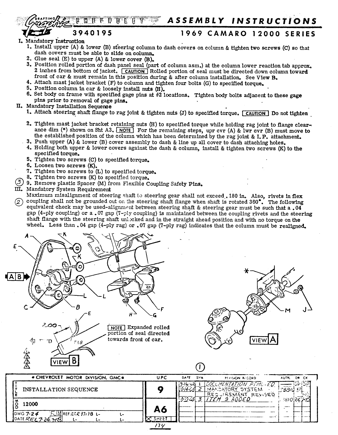
w A s s EM s L Y IN s r R u c rs o N s 3940195 1969 CAMARO 12000 SERIES 1 Maikcamry insu iieuon l Install upper A lower B steering column to dash covers on column tt tightentwo screws C so that dash covers must be able to slide on column 2 Glue seal E to upper A tt lower cover B 3 Position rolled portlon of dash panel seal part of column asm at the column lower reactlon tab approx Z inches from bottom of jacket HIDE Rolled portion of seal must be directed down column toward front of car must remain Ln this position during after column installation See View B 4 Attach mast jacket bracket F to column and tlgiten four bolts G to specified torque 5 Position column in car loosely install nuts O 6 Set body on frame with specified gage pins at 2 locations Tlghtenbody bolts adjacent to these gage pins prior to removal of gage pins ll Mandatory lnstallatlon Sequence 1 Attach steering shalt Clange to rag joint Sz tighten nuts J to specified torque IHLEIEII Do not tighten 2 Tighten mast jacket bracket retalnlngnuts H to specified torque while holding rag joint to flange cle r ance dim shown on Sht A3 IIE For the remaining steps upr cvr A lwr cvr B must move to the established position of the column which has been determined by the rag joint 1 P attachment 3 Push upper A Ez lower B cover assembly to dash line up all cover to dash attaching holes 4 Holding both upper lower covers against the dash column install tlgzten two screws K to the specified torque 5 Tighten two screws C to specified torque 6 Loosen two screws K 7 Tighten two screws to L to specified torque 8 Tighten two screws K to speciiled torque 9 Remove plastic Spacer M from Flexible Coupling Safety Plus III lvlandatory System Requirement Mazdmum mlsalignment of steering shaft to steering gear shall not exceed 180 ln Also rivets ln flex coupling shall not be grounded out on the steering shaft flange when shaft is rotated 3B0 The following equivalent check may be used alignment between steering shaft steering gear must be such that a 04 gap 4 ply coupling or a 07 gap 7 ply coupling Ls maintained between the coupling rivets and the steering shaft Range with the steering shaft unlocked and in the straight ahead position and with no torque on the wheel Less than 04 gap 4 ply rag or 07 gap 7 ply rag indicates that the column must be reallgned A X ie U Wx l L i 5 K mm s a n A l A j Q JQ Q 1 q 5 1 L L L L 5 Q B K r 9 e je g L M J L E H G e 001 Expanded rolled portion of seal directed I pn F D rm towards mm of ea vasw A Q g ww CHEVIOLEV Moms oevnsoon cues urs our sw l S O r e LL som L rj I ida A QQQVQMNIAQ MF 7 Z P F i HQSTALLATION SEQUENCE 2 J E i I R1 5 TE 555 nl ttl Q RE c R 5A y xT Rayiseo l M FMAAODED L wow g 12000 a owc 7 2 V Jlnznacz 771 B L L LQ i Q nm 2 4 t L L K I 1 2 Z