Jeep Parts Wiki | Ford Parts Wiki
Home | Search | Browse | Marketplace | Messages | FAQ | Guest
Prev
 Next
Next
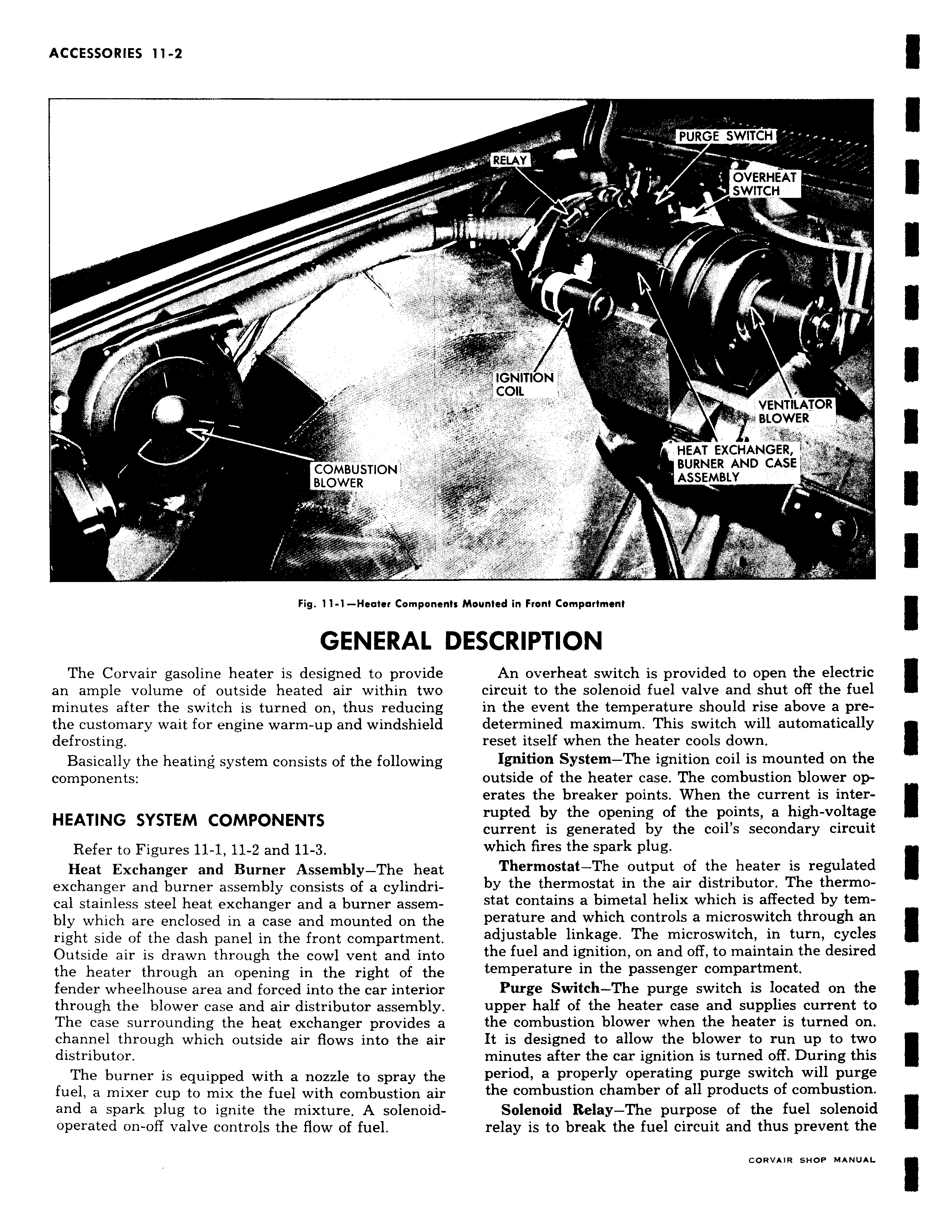
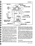
I COMBUSTION BLOWER l Fig 11 1 Heater Component GENERAL The Corvair gasoline heater is designed to provide an ample volume of outside heated air within two minutes after the switch is turned on thus reducing the customary wait for engine warm up and windshield defrosting Basically the heating system consists of the following components HEATING SYSTEM COMPONENTS Refer to Figures 11 1 11 2 and 11 3 Heat Exchanger and Burner Assembly The heat exchanger and burner assembly consists of a cylindrical stainless steel heat exchanger and a burner assembly which are enclosed in a case and mounted on the right side of the dash panel in the front compartment Outside air is drawn through the cowl vent and into the heater through an opening in the right of the fender wheelhouse area and forced into the car interior through the blower case and air distributor assembly The case surrounding the heat exchanger provides a channel through which outside air flows into the air distributor The burner is equipped with a nozzle to spray the fuel a mixer cup to mix the fuel with combustion air and a spark plug to ignite the mixture A solenoidoperated on off valve controls the flow of fuel PURGE SWITCH F RELAY OVERHEAT f SWITCH IGNITION COIL i VENTILATOR BLOWER m a HEAT EXCHANGER BURNER AND CASE ASSEMBLY a7j I 1 c Mounted in Front Compartment ESCRIPTION An overheat switch is provided to open the electric circuit to the solenoid fuel valve and shut off the fuel in the event the temperature should rise above a predetermined maximum This switch will automatically reset itself when the heater cools down Ignition System The ignition coil is mounted on the outside of the heater case The combustion blower operates the breaker points When the current is interrupted by the opening of the points a high voltage current is generated by the coil s secondary circuit which fires the spark plug Thermostat The output of the heater is regulated by the thermostat in the air distributor The thermostat contains a bimetal helix which is affected by temperature and which controls a microswitch through an adjustable linkage The microswitch in turn cycles the fuel and ignition on and off to maintain the desired temperature in the passenger compartment Purge Switch The purge switch is located on the upper half of the heater case and supplies current to the combustion blower when the heater is turned on It is designed to allow the blower to run up to two minutes after the car ignition is turned off During this period a properly operating purge switch will purge the combustion chamber of all products of combustion Solenoid Relay The purpose of the fuel solenoid relay is to break the fuel circuit and thus prevent the RVSIR aunP MANUAL