Jeep Parts Wiki | Ford Parts Wiki
Home | Search | Browse | Marketplace | Messages | FAQ | Guest
|
Corvair Chassis Shop Manual Supplement December 1965 |
|
Prev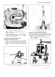

 Next
Next
REAR AXLE AND REAR SUSPENSION 4 4 4v n u N V V inf Y 5 in T e RAE i I it VQ do an Ent A P ERRE i t ia r i 4 4 ARRE LEEA if S R44 4R 4Ri EE i i A 4 T c F S E i i R 4 f 1 a r r 2 R u 4R4 AARER u RRREER n A r i AEE4 fri er 4 r V A EERTEM V r S yy S y i i T i EE EE R 4 E5 i i P E4 E It T i i ZIE gf R r i A Fig ii Measuring Pinion Turning Torque NOTE At this point the differential bearings Fig 9 Adiusting Ring Geor to Pinion are pre O3 ded 1 ht ht d b d t 1 th 5 Install differential side bearing adjusting sleeve Tie en nie Si e eaiine a ineine S eeve wi ieeiung tabs to prevent loss of adjustment Teel 8342 Wnr1e rocking the differential eeeembly 6 Back off pinion adjusting sleeve as required with until there is zero back13 Sh b tWo I1 th Ylllg g I Tool J 972 to eliminate any pinion bearing p1 103d ang pinien flea 9 Mark iliieieeini en bein Sleeve ng 10 then measure the turning torque created an enrrrer W1 erayen Or Penel by the side bearing preload at the pinion using Tool 2 Tighten left side bearing adjusting sleeve until bear 8362 Adapter and an inch pound torque wrench ing and race are at point of contact Mark this point Such as J 5853 ria 11 Record this reading eX en bein aeliiieiine Sleeve and carrier ample 8 in lbs Then retignten the pinion bearing 3 Beck eff right Side ajiiieiine Sleeve three te grrr adjusting sleeve to increase the initial turning torque netenee ie eliininaie 0 ring Wind nn Re ie en by 4 6 in lbs with used bearings or 9 11 in lbs 4 Sleeve in ene neien ieeee freni new bael laSii inanle with new bearings Using the 8 in lbs initial turning Back off left side adjusting sleeve to re ease any tordue from our exaiinple the final total turning 0 ring win i p inen reiielnen aiiiiieiine Sleeve torque measured at the pinien would be 12 14 in lbs until marks realign plus a minimum of two additional with used bearings or iq ig in lbs with new notches and a maximum of three additional notches bearings te align the Sleeve notches fen leekine tab 7 Install pinion adjusting sleeve locking tab installation Ring Geur und Pinion Contact Puttern do a Upon completion of the ring gear to pinion backlash i adjustment a check of the gear teeth contact pattern i should be made to ensure gear life and minimize bearing r P P i it r noise from the carrier i 1 Thoroughly clean the ring gear and pinion teeth with i iiei it i rrcd B solvent and air dry V i K d t 2 Paint ring gear teeth only with a light and even h e r M A r ine 4 coating of a mixture of iron oxide gear marking e i r compound of a suitable consistency to produce a xx contact pattern on the ring gear 3 While firmly holding the pinion with a rag to form a friction brake turn the ring gear back and forth ig t VI with a wrench fig 12 on the ring gear mounting 4 bolts until a definite contact pattern is formed 4 Inspect the contact pattern produced and analyze the it T ei ii ieeiiiie ieieiive ie ine renewing eaia Fieiiie li rovides gear tooth nomenclature and Figure 14 5 t ei i iii iiiir p i j i e i illustrates the various contact patterns which may t i zz 1 ii e L if rrp The large end of the tooth is called the heel and the small end the toe Also the top of the tooth Fig iO Tightening Pinion Beoring Adjusting Sleeve which is the p I t above th pii Ch 11116 is called the CORVAIR SHOP MANUAL SUPPLEMENY