Jeep Parts Wiki | Ford Parts Wiki
Home | Search | Browse | Marketplace | Messages | FAQ | Guest
|
Corvair Chassis Shop Manual Supplement December 1965 |
|
Prev

 Next
Next
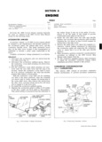
REAR AXLE AND REAR SUSPENSION 4 6 Pour a liberal quantity of rear axle lubricant on A i gears and bearings and turn gears to work lubricant i into all surfaces fl n 5 Place a new differential carrier cover gasket on the carrier then install cover Tighten cover bolts to i Si ifiu u S r l 6 Fin differential carrier to a level even with me V igia finer ping opening t L i a g Wheel Spindle and Support v e I 4 aae l J j I R g i i t E q P S uI Iv e 21 8 1 1 Position spindle support over torque arm studs then gpgl I g Sll I l liy position brake flange plate and shoe assembly over V VV I I VVAS S support and studs Connect parking brake cable to g il L actuating lever Torque stud nuts to specifications i r Q 2 Install wheel spindle bearing cups in the support using Tool J 8850 for outer beerius aud T 1 J 7817 vel u i I ril 5 Q rrsi u eien f01 i 1 b 11 i g 1 3 The wheel spindle spindle support spindle bearings I and the spindle bearing spacer are the various items l I that affect wheel bearing end play Therefore when v W iy p replacing any of the aforementioned items it will Q A i ffl I QI be necessary to ascertain proper adjusting shim thickness to maintain specified end play Select the I it I I ll E it ii E E shim thickness using Tool J 21836 as follows a Remove the knurled nut from each end of Gauge J 21836 Fig l6 G ugmg Wheel Becrmg Shim Requirement b Position spindle inner bearing on small end of against spacer fig 15 Install under cut end of gauge small end of bearing toward pin on knurled nut against bearing and hand tighten nut gauge then finger tighten knurled nut against so that there is no play in the gauge body bearing e Install dial indicator J 8001 and position indi c Position gauge and bearing assembly through the cator finger against moveable shaft of J 21836 inboard side of spindle support fig 16 d Install bearing spacer over large end of gauge f Move shaft of J 21836 so that it travels the then position spindle outer bearing on gauge and maximum permissible distance limited by spacer and inner bearing v g Record reading obtained in Step f recheck to I V I ensure accuracy I l I I y h To the reading obtained in Step f add 0 097 The u M W J total obtained is the required shim thickness wk l necessary to maintain specified end play EXAMPLE Dial indicator reading obtained in Step f 0 026 P Add 0 097 to dial indicator reading 0 097 Gauge J 21836 is constructed to H g represent the smallest shim which lnl T j l is QO97 u I Il Shim thickness required TOTAL O 123 THREAD N ASSEMBLE Shim to be installed would be O l24 thick since UNDER gg WL INNER END this is the shim with a thickness nearer to the TO BRG lg i FIRST value as computed above h N I I i 4 Disassemble gauge and install spindle outer bearing f aaa f Pack both wheel bearings with a high melting point V wheel bearing lubricant prior to installation Al V V H l 5 Position support outer seal on Tool J 21842 align e l V l l Z tabs in seal with slots in tool install seal in support LOCATE M A and connect brake line INDICATOR ON gf 6 Reassemble spindle to spindle support CENTER 5l FT Il I 7 Reassemble axle drive shaft brake drum and wheel I and tire assembly torque wheel stud nuts to specifications Fig 15 SpindIe Benring Gauge Instolloiion 8 Bleed brakes as outlined in Section 5 CORVAIR SHOP MANUAL SUPPLEMENT