Jeep Parts Wiki | Ford Parts Wiki
Home | Search | Browse | Marketplace | Messages | FAQ | Guest
|
Corvair Chassis Shop Manual Supplement December 1965 |
|
Prev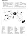

 Next
Next
3869499
3869499
3877877
3877877
3872878
3872878
3872879
3872879
THREE SPEED TRANSMISSION 7 9 disengaging the carpet and moving it out of the way NOTE Disconnect Seal from Shield by gmSp 1 Remove the front underbody tunnel cover ing at lower edge and pulling groove of seal off 2 Remove four nuts from the underside of the floor Of Shield flanges shift unit 3 Lift the entire shift lever assembly upward to dis 2 Disconnect starter motor wires at quick disconnect engage it from the shifter tube pocket and floor pan Disconnect both battery cables at battery to avoid Nora A hard plastic seai with Shouidered battery pqstdamfge when Qngitw iS1 W r d 3 If so equipped disconnect radio ground straps at left stud holes upper seal should be on top of the and right Shieids 1001 pam and 3 Hat hard plastic www Seal 4 Raise vehicle and support on jack stands then re should be between the shifter tube bracket and move reabcemer Shield the underside of the floor pan Retain these 5 P1 1 ft wth QTO 1 7894 tmched under seals and any stamped steel shim plates for we mgm 1 1 O A engine and support weight of engine posslble remstallatlom Dlscard any Hat Washers 6 Loosen two engine rear mount nuts until nuts are used for shims flush with end of stud 4 Obtain a micrometer measurement of the floor pan 7 Disconnect fuel line from body clip so that line can thickness at all four sides of the opening Compare spring away from floor pan the average measurement to the Dimension A 8 To allow clearance for the transaxle to swing down column in the following chart to determine what loosen the front upper bolt from each rear strut rod lower seal is to be used and what quantity of steel bracket at the differential a few turns to relieve shim plates if any are required tension on the lock washer Remove the other three on each side LOWER SEAL SHIM 9 Disconnect accelerator rods at transmission DIM 3869499 3877877 3872878 3872879 b uCmnk l A T 10 Disconnect left and right front strut rod brackets at WHITE GREEN BLACK STEEL engine front mount bracket P Wt 11 Disconnect the clutch fork pull rod and spring at the 090 104 1 2 clutch cross shaft Loosen the nut attaching the 105 118 l 1 cross shaft to the engine front mount The cross 119 133 1 shaft can be rotated and pushed up out of the way 134 147 1 12 Disconnect shift rod coupling at transmission shift 148 161 l 3 rod 162 178 1 2 13 Disconnect emergency brake return spring at front i 179 193 1 1 mount bracket mi 209 1 14 If S0 equipped remove back up lamp switch wiring 15 Lower front of engine enough for transmission to After Selecting the proper lower Seal and Shim Stock clear underbody on removal Remove bolts retaining coat all surfaces of the seals and shims with white grease Assemble shims if any over the shoulders of I Knob 5 Spring D g Nur II Screwdnsco the upper seal and install this pack on the upper surface 2 Housing Assy 6 Bushing m gOOr 05OO I2 Retcinernosoo of the floor pan Insert the correct lower seal between 3 Lever Assy 7 Cup I3 Cover the shifter tube bracket and under surface of the floor A Upper Sem 8 Lower Sem I4 e Assy pan As an aid in reassembly a short sheet metal screw H 13 I5 NUI may be installed through the shifter tube reinforcement 17 M 6 E k and into the underside of the floor pan to hold the lower I4 7 J N unit stationary while installing the shift lever assembly FORWARD 1 Ijig 5 Q Reinstall the four retaining nuts and torque to 8 ft lbs I 2 V I I The temporary holding screw must now be removed to permit the entire shift assemblyto slide on the floor pan VIEW A 4 fir SO 2 A B in reaction to powertrain movement Reinstall all other NOTE Install h vusw C S fy 3 previously removed components fig 12A wml relief Ow rg E MODEL 10700 of vehicIe used to lock L 4 SHIFT ADJUSTMENT mg purr of scar QI 5 Refer to Figure 13A for the proper adjustment 6 C J E 6 procedure 10 T L 7 5 8 MANUAL TRANSMISSION REMOVAL CARPET 1 A II A p K 1 6 The following is an improved service procedure for 12 49 TUBE AND removing either a 3 or 4 speed transmission This new MOELEELWWZOO ROD Assy procedure should be used in place of the 17 step proce 6 B LbS dure detailed for transmission removal on Page 7 27 of L Lube G S mb YUPPE Hm2D l2gE 9 the 1965 Corvair Chassis Shop Manual 1 Disconnect engine seal at front shield left and right SjdgS Fig I2 3 8 4 Speed Georsbitt Control CORVAIR SHOP MANUAL SUPPLEMENT