Jeep Parts Wiki | Ford Parts Wiki
Home | Search | Browse | Marketplace | Messages | FAQ | Guest
|
Corvair Chassis Shop Manual Supplement December 1965 |
|
Prev

 Next
Next
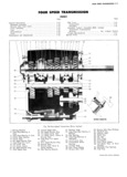
THREE SPEED TRANSMISSION 7 I0 t1 3 SmiSSi0 to diffofolltial 31l0WiHg t1 21 S X1 to 16 For installation of transmission reverse removal partially drain then remove transmission from prooodoros differential NOTE If a 3 or 4 speed transmission is re NOTE TI IlSITllSSlOI 1 input shaft I 1 I13 i1 1S I1 placed without backup lights be Surg an QX eagod iu olutoh aud will protrudo out through pension plug is insmiied in repiaeemem differential Transmission is removed with front transmission lamp switch hole mount bracket attached 1 s 26 S l UPP 6 L Washer ll Washer 20 Lmk 23 27 2 Sea Lower 7 Nut I2 Coupling Assy 2I Retainer 3 Tube Assy 8 Clamp I3 Pin 22 Grommets 25 Z lQ 4 Rod Assy 9 Pin T4 Anchor 23 Bushing 5 Bolt IO C Pin T5 Nut 24 Silencer Tube I6 wqsher 25 sw VIEW A lg 1 CL CH CONTROL J sj l 1 7 B 26 I noo soot Assr 18 gon 27 Boot Assy aw io www 28 Shim J l 28 X UNDEQEQQB EAnsl nrt uNi Aes 1 I2 1 SCREWS ADJUSTMENT 2 10 mf J I PIace transmission in re A gi 3 verse gear and block as 4 5 IX 13 necessary to retain detent 6 I Z 9 8 14 throughout gearshift adiust r t a 24 Q 0 il Q 2 Remove lash from system FORWARD J F Ti by pushing rearward lightly Q k o I I5 on forward end of long shift 23 ii v s l rod Proper linkage adjust ment is provided if position Y IT iz d A fi A I6 N Y ing of the fulcrum block l A 5 I 1 V 1 6 il EiiZL Zi ZT Y d r V 6 l 3 If linkage readiustment is 2Q FRONT FACE OF required loosen rear coup 3 FULCRUM BLOCK ling clamp and change 2 2l C lP Fl i Rod ASSY effective length of rod to 0 I5 L OF FRONT ATTACHING 7 ir l2 l6 i bS TT STUDS ON HOUSING ie 3 speedt obtain corrett setting Tight 0 3 4 Lbs ft 22 l A 4 SP dl en clamp Io secure coupling 0 4 2g bs WITH TRANS IN REVERSE to rod assembly 0 ii 1su ro Fig l3A 3 4 Speed Shift Linkage Installation Acliustment convm soo MANUAL sopmenmr