Jeep Parts Wiki | Ford Parts Wiki
Home | Search | Browse | Marketplace | Messages | FAQ | Guest
|
Corvair Chassis Shop Manual Supplement December 1967 |
|
Prev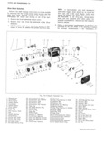
 Next
Next
3869499
3869499
38771377
38771377
3872878
3872878
3872879
3872879
CLUTCH AND TRANSMISSIONS 7 9 column in the following chart to determine what K b H suewlom lower seal is to be used and what quantity of steel H A 5 iP L l9 9 N I2 Rctuinemosoo shim plates if any are required 3 l s Y C p g B 5 ui Cover 14 S IA LOVVER SEAL SHIM 4 Upper Sem 8 Lower e in I5 N SSY DIM 3869499 38771377 3872878 3872879 11 13 16 nmckee A r 4 17 J Nul 090 104 1 2 L K 105 118 1 1 4 view A s e 2 119 133 1 5 Q A 134 147 1 NOTE lnslcll housing VIEW C 3 148 J6 1 3 with relief toward from MODEL 10700 162 178 1 2 of vehicIe used to lock m 4 179 193 1 1 ng pun of sem 5 194 209 1 C 7 6 El After selecting the proper lower seal and shim stock 10 coat all surfaces of the seals and shims with white CARPET ll b grease Assemble shims if any over the shoulders of TAN6 the upper seal and install this pack on the upper surface 12 of the floor pan Insert the correct lower seal between VIEW B Il 2 the shifter tube bracket and under surface of the floor MODEL 5 pan As an aid in reassembly a short sheet metal screw CD u UPPER AND LOWER 9 may be installed through the shifter tube reinforcement m L b b Y H M K SEALS and into the underside of the floor pan to hold the lower unit stationary while installing the shift lever assembly F 2A 3 d 4 S d G I C l Reinstall the four retaining nuts and torque to 8 ft lbs Ig On pee eww I who The temporary holding screw must now be removed to permit the entire shift assembly to slide on the floor pan 8 To allow clearance for the transgxle to swing down in reaction to powertrain movement Reinstall all other loosen the front upper bolt from each rear strut rod previously removed components fig 12A bracket at the differential a few turns to relieve tension on the lock washer Remove the other three SHIFT ADJUSTMENT On each Sme 9 Disconnect accelerator rods at transmission Refer to Figure 13A for the proper adjustment bellcramg procedure 10 Disconnect left and right front strut rod brackets at engine front mount bracket MANUAL TRANSMISSION REMOVAL 11 Disconnect the clutch fork pull rod and spring at the clutch cross shaft Loosen the nut attaching the The following is an improved service procedure for CFOSS Shaft to tht gi fi 0 t m0 t Th CYOSS removing either a 3 or 4 speed transmission This new Shaft can be rotated and pushed up out of the way procedure should be used in place of the 17 step proce 12 Disconnect shift rod coupling at transmission shift dure detailed for transmission removal on Page 7 27 of rod the 1965 COYVZUY Chassis Sh P Manual 13 Disconnect emergency brake return spring at front 1 Disconnect engine seal at front shield left and right mount bracket 5j dgS 14 If so equipped remove back up lamp switch wiring NOTE Disconnect seal from shield by grasp 15 LIOWGT ion gf Engine Qmiugg fOr tI m m1SiiC n tO ing at lower edge and pulling groove of seal Sear Lln tr Oty I f mO ai EQIIOYG mt S re afmig Off Of Shield flanges ransmission lo 1 eren ia a owing ransax e o partially drain then remove transmission from 2 Disconnect starter motor wires at quick disconnect differential Disconnect both battery cables at battery to avoid battery post damage when engine is lowered NOTE Trzmsmlssmn input Shaft remams Gn gaged in clutch and will protrude out through 3 If so equipped disconnect radio ground straps at left differential Transmission is removed with front and mgm Sh1 1dS mount bracket att ched 4 Raise vehicle and support on jack stands then re a move realucenter Shield 16 For installation of transmission reverse removal 5 Place engine lift with Tool J 7894 attached under rocedums engine and support weight of engine p 6 Loosen two engine rear mount nuts until nuts are NOTE lf a 3 or 4 speed transmission is re flush with end of stud placed without backup lights be sure an ex 7 Disconnect fuel line from body clip so that line can pansion plug is installed in replacement spring away from floor pan transmission lamp switch hole CORVAIR SHOP MANUAL SUPPLEMENT