Jeep Parts Wiki | Ford Parts Wiki
Home | Search | Browse | Marketplace | Messages | FAQ | Guest
|
Corvair Chassis Shop Manual Supplement December 1967 |
|
Prev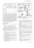

 Next
Next
CLUTCH AND TRANSMISSIONS 7 10 I I I UPP f 6 L Washer 11 Washer 20 Link 2 23 26 27 2 I I 7 N 12 Coupling Assy 21 Retainer sj 3 Tube Assy 8 Clqmp 13 Pin 22 Grommets i IL 4 A 23 1 25 Assss 5 It 10 C Pin Q ts Nut 24 snenrerrube I cz L 2 Il Y 16 Washer 25 Boot VIEW A rr 1 t7 Bracket Q 26 Screw e as lUTCH CONTROL I 18 Bolt 27 Boot Assy I ROD BOOT AssY 9 w h 28 Shim e 28 as er UNDERBODY k l 7 SHIELD GEARSHIFT LINKAGE s 12 CR5w5 ADJUSTMENT 9 1 2 10 11 1 P ace transmission in re M 3 verse gear and block as 4 5 I necessar to r t dt t 7 sf 1 throughairt ga 3 7 s i a gus e I 1 E 3 14 O l r I 2 Remove lash from system FORWARD 15 by pushing rearward lightly V U I on forward end of long shift 23 Q 3 s 7 rod Proper linkage adjust Q Q A Rod A ment is provided if position X 1 All y 1716 Y ing of the trrtrrrrm block j 4 6 6 approximates that specified l in illustration at left y I6 10 3 lf linkage readiustment is 20 i r FRONT FACE OF required loosen rear coup n 2 18 L CK Illtg cl mp and change 0 2 6Lb n 5 21 CL gp FRQNT A TACHING 5Y eH ective length of rod to 6 STUDS ON HOU5 N ly H obtain correct setting Tight 3 4 Lb ll 22 en clamp to secure coupling Q 14 22 Lbs tt WITH TRANS IN REVERSE to rod assembly Q 11 tsibs n Fig l3A 3 and 4 Speed Shift Linkage installation and Adiustment INDEX Page Page General Description 7 10 Side Cover 7 12 Blainshaft Assembly 7 10 Disassembly 7 12 Reverse Idler Gear Parts 7 10 Assembly 7 12 Cover Assembly 7 ll Gearshift Control Assembly Shift Linkage Case 7 11 Adjustment Transmission 7 13 Miscellaneous 7 12 Removal r See 3 Speed Section Tools 7 12 Torque Specifications 7 13 Maintenance and Adjustments 7 12 Spoojal Tools 7 15 A great deal of similarity and interchangeability now rather than the first and reverse shift Gear teeth cut in exists between the new 3 and 4 speed transmissions the first and second synchronizer sleeve distinguish it Only these 4 speed differences as they affect service from the third and fourth synchronizer sleeve All parts will be covered here Other 4 speed service procedures except the gears and the first and second synchronizer are similar to the Corvair 3 speed transmission and sleeve in the new four speed transmission mainshaft are not repeated in this section assembly are also used in the Corvair three speed transmission mainshaft assembly However starting from the front gears on the mainshaft are third second MAINSHAFT ASSEMBLY and first rather than second first and reverse A fourth Assembly procedures described under Corvair Three blocker ring is used between the 1 2 synchronizer as Speed Transmission also apply to this transmission sembly and first gear on the four speed transmission However the synchronizer assembly at the front of the mziinshaft is used for the third and fourth rather than the REVERSE IDLER GEAR PARTS second and third shift The synchronizer assembly at the This is a gding reverse idler gear and shaft retained rear of the mainshaft is used for the first and second b a woodruff key Addition of a snap ring stop to limit Y CORVAIR SHOP MANUAL SUPPLEMENT