Jeep Parts Wiki | Ford Parts Wiki
Home | Search | Browse | Marketplace | Messages | FAQ | Guest
|
Corvair Chassis Shop Manual December 1964 |
|
Prev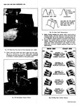
 Next
Next
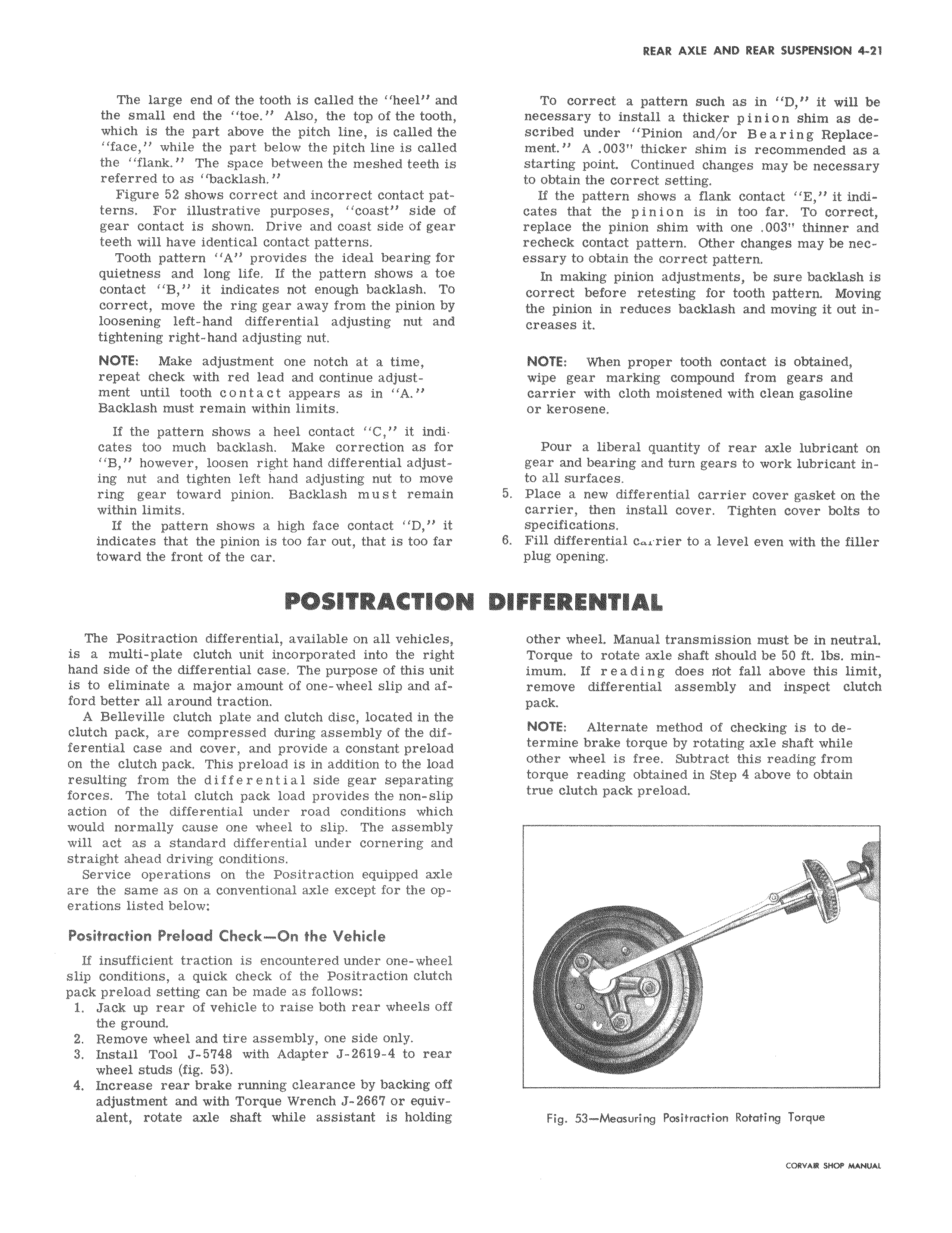
The large end of the tooth is called the heel am the small end the toe Also the top of the tooth which is the part above the pitch line is called the face while the part below the pitch line is callec the flank The space between the meshed teeth if referred to as backlash Figure 52 shows correct and incorrect contact patterns For illustrative purposes coast side oi gear contact is shown Drive and coast side of gear teeth will have identical contact patterns Tooth pattern A provides the ideal bearing for quietness and long life If the pattern shows a toe contact B it indicates not enough backlash To correct move the ring gear away from the pinion by loosening left hand differential adjusting nut and tightening right hand adjusting nut NOTE Make adjustment one notch at a time repeat check with red lead and continue adjustment until tooth contact appears as in A Backlash must remain within limits If the pattern shows a heel contact C it indicates too much backlash Make correction as for B however loosen right hand differential adjusting nut and tighten left hand adjusting nut to move ring gear toward pinion Backlash must remain within limits If the pattern shows a high face contact D it indicates that the pinion is too far out that is too far toward the front of the car POSITRACTIO The Positraction differential available on all vehicles is a multi plate clutch unit incorporated into the right hand side of the differential case The purpose of this unit is to eliminate a major amount of one wheel slip and afford better all around traction A Belleville clutch plate and clutch disc located in the clutch pack are compressed during assembly of the differential case and cover and provide a constant preload on the clutch pack This preload is in addition to the load resulting from the differential side gear separating forces The total clutch pack load provides the non slip action of the differential under road conditions which would normally cause one wheel to slip The assembly will act as a standard differential under cornering and straight ahead driving conditions Service operations on the Positraction equipped axle are the same as on a conventional axle except for the operations listed below Positraction Preload Check On the Vehicle If insufficient traction is encountered under one wheel slip conditions a quick check of the Positraction clutch pack preload setting can be made as follows 1 Jack up rear of vehicle to raise both rear wheels off the ground 2 Remove wheel and tire assembly one side only 3 Install Tool J 5748 with Adapter J 2619 4 to rear wheel studs fig 53 4 Increase rear brake running clearance by backing off adjustment and with Torque Wrench J 2667 or equivalent rotate axle shaft while assistant is holding D thicker pinion w de scribed and or Bearing recommended as a starting Continued necessary obtain the correct setting If the contact indi cates n is in too far To correct pinion v with one m inn v O essary to obtain the correct pattern In making pinion adjustments be sure backlash is correct before retesting for tooth pattern Moving pinion moving creases it NOTE When proper tooth contact is obtained wipe gear marking compound from gears and carrier with cloth moistened with clean gasoline or kerosene Pour a liberal quantity of rear axle lubricant on 5 Place a new differential carrier cover gasket on the carrier then install cover Tighten cover bolts to specifications 6 Fill n a level even with the finer in neutral Torque should 0 e this limit remove method v determine ine brake torque by rotating axle shaft while other wheel is free Subtract this reading from torque reading obtained i e to obtain reload Fig 53 Measuring Positraction Rotating Torque