Jeep Parts Wiki | Ford Parts Wiki
Home | Search | Browse | Marketplace | Messages | FAQ | Guest
|
Corvair Chassis Shop Manual December 1964 |
|
Prev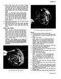
 Next
Next
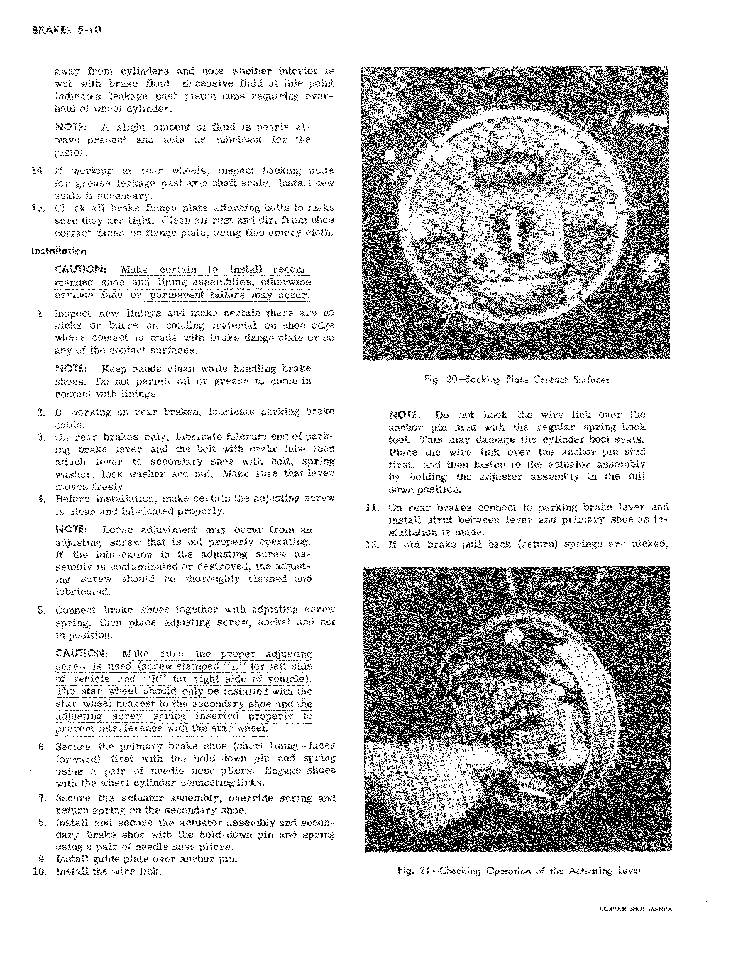
away from cylinders and note whether interior isl wet with brake fluid Excessive fluid at this point indicates leakage past piston caps requiring over i haul of wheel cylinder NOTE A slight amount of fluid is nearly al ways present and acts as lubricant for the piston 14 If working at rear wheels inspect backing platc for grease leakage past axle shaft seals Install ne seals if necessary 15 Check all brake flange plate attaching bolts to sure they are tight Clean all rust and dirt from shm contact faces on flange plate using fine emery cloth InsMllation CAUTION Make certain to install recom mended shoe and lining assemblies otherwise serious fade or permanent failure may occur 1 lnspect new linings and make certain there are no nicks or burrs on bonding material on shoe edge where contact is made with brake flange plate or on any of the contact surfaces NOTE Keep hands clean while handling brake shoes Do not permit oil or grease to come in contact with linings 2 If working on rear brakes lubricate parking brak cable 3 On rear brakes only lubricate fulcrum end of park ing brake lever and the bolt with brake lube them attach lever to secondary shoe with bolt spring washer lock washer and nut Make sure that lever moves freely I 4 Before installation make certain the adjusting screv is clean and lubricated properly I NOTE Loose adjustment may occur from an adjusting screw that is not properly operating If the lubrication in the adjusting screw as i sembly is contaminated or destroyed the adjusting screw should be thoroughly cleaned and lubricated 5 Connect brake shoes together with adjusting screw spring then place adjusting screw socket and nut in position CAUTION Make sure the proper adjusting screw is used screw stamped L for left side of vehicle and R for right side of vehicle The star wheel should only be installed with the star wheel nearest to the secondary shoe and the adjusting screw spring inserted properly to prevent interference with the star wheel 6 Secure the primary brake shoe short lining faces forward first with the hold down pin and spring using a pair of needle nose pliers Engage shoes with the wheel cylinder connecting links 7 Secure the actuator assembly override spring anCi return spring on the secondary shoe 8 Install and secure the actuator assembly and secon dary brake shoe with the hold down pin and spring using a pair of needle nose pliers 9 Install guide plate over anchor pin i 10 Install the wire link r Fig 20 Backing Plate Contact Surfaces NOTE Do Dot hook the wire link over the anchor pin stud with the regular spring hook tooli This may damage the cylinder boot seals Plate the wire link over the anchor pin stud first and then fasten to the actuator assembly by holding the adjuster assembly in the full doaIn position 11 On rear brakes connect to parking brake lever and install strut between lever and primary shoe as installation is made 12 If old brake pull back return springs are nicked i a Fib 21 Checking Operation of the Actuating Lever CORVAR 5110P MANUAL