Jeep Parts Wiki | Ford Parts Wiki
Home | Search | Browse | Marketplace | Messages | FAQ | Guest
Prev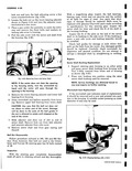
 Next
Next
605142
605142
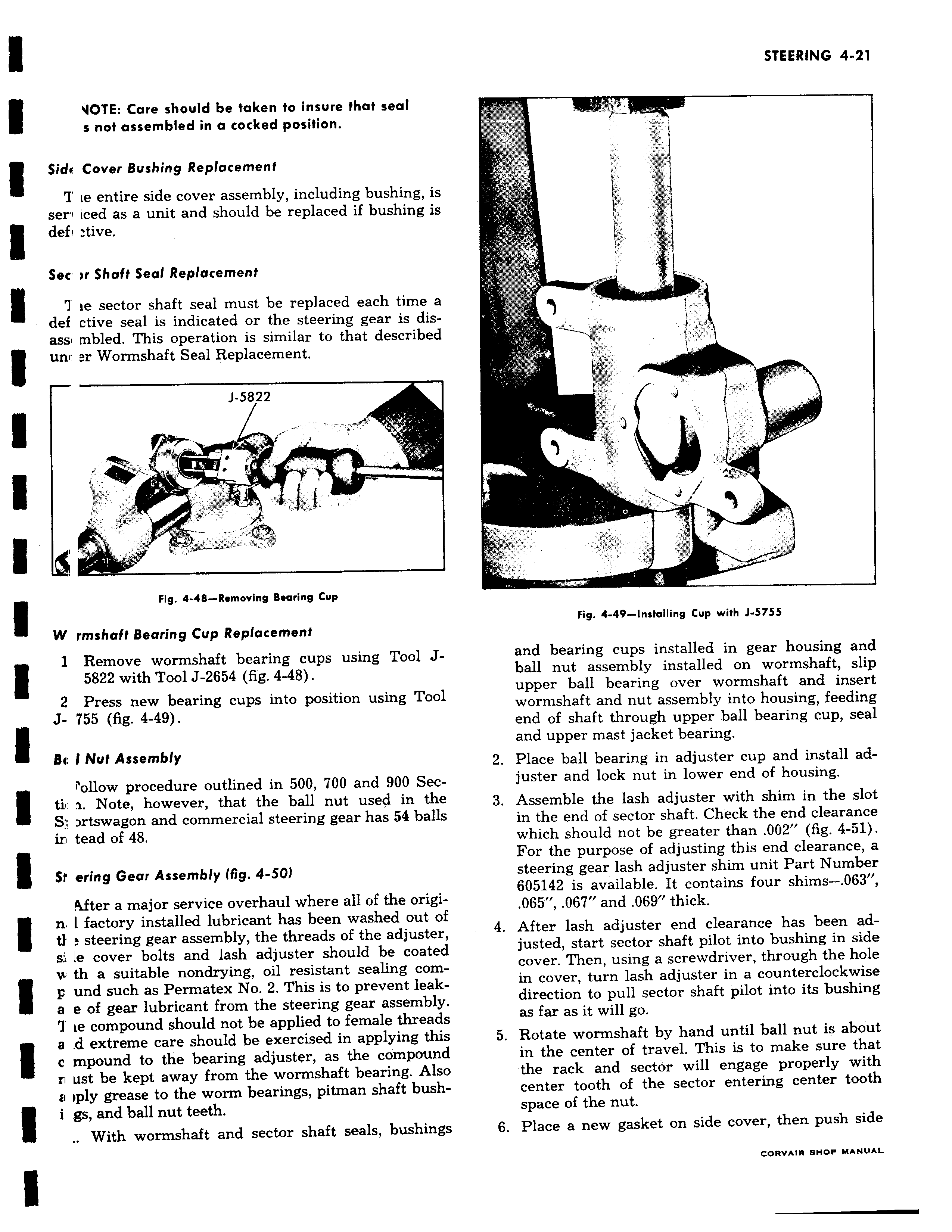
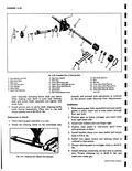
VOTE Care should be taken to insure that seal is not assembled in a cocked position Sidi Cover Bushing Replacement Z ie entire side cover assembly including bushing is serv iced as a unit and should be replaced if bushing is defi tive Sec m Shaft Seal Replacement 7 ie sector shaft seal must be replaced each time a def ctive seal is indicated or the steering gear is disass mbled This operation is similar to that described I un er Wormshaft Seal Replacement J 5822 1 z Fig 4 48 Removing Bearing Cup W rmshaft Bearing Cup Replacement 1 Remove wormshaft bearing cups using Tool J5822 with Tool J 2654 fig 4 48 2 Press new bearing cups into position using Tool J 755 fig 4 49 Bi 1 Nut Assembly Ulow procedure outlined in 500 700 and 900 Secti a Note however that the ball nut used in the S rtswagon and commercial steering gear has 54 balls ir tead of 48 St ering Gear Assembly fig 4 50 Mter a major service overhaul where all of the origin l factory installed lubricant has been washed out of tl steering gear assembly the threads of the adjuster s le cover bolts and lash adjuster should be coated w th a suitable nondrying oil resistant sealing comp und such as Permatex No 2 This is to prevent leaka e of gear lubricant from the steering gear assembly T ie compound should not be applied to female threads a d extreme care should be exercised in applying this c mpound to the bearing adjuster as the compound zi ust be kept away from the wormshaft bearing Also ii iply grease to the worm bearings pitman shaft bushi gs and ball nut teeth With wormshaft and sector shaft seals bushings i i i r 1 Fig 4 49 installing Cup with J 5755 and bearing cups installed in gear housing and ball nut assembly installed on wormshaft slip upper ball bearing over wormshaft and insert wormshaft and nut assembly into housing feeding end of shaft through upper ball bearing cup seal and upper mast jacket bearing 2 Place ball bearing in adjuster cup and install adjuster and lock nut in lower end of housing 3 Assemble the lash adjuster with shim in the slot in the end of sector shaft Check the end clearance which should not be greater than 002 fig 4 51 For the purpose of adjusting this end clearance a steering gear lash adjuster shim unit Part Number 605142 is available It contains four shims 063 065 067 and 069 thick 4 After lash adjuster end clearance has been adjusted start sector shaft pilot into bushing in side cover Then using a screwdriver through the hole in cover turn lash adjuster in a counterclockwise direction to pull sector shaft pilot into its bushing as far as it will go 5 Rotate wormshaft by hand until ball nut is about in the center of travel This is to make sure that the rack and sector will engage properly with center tooth of the sector entering center tooth space of the nut 6 Place a new gasket on side cover then push side CORVAIR SHOP MANUAL