Jeep Parts Wiki | Ford Parts Wiki
Home | Search | Browse | Marketplace | Messages | FAQ | Guest
Prev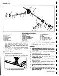

 Next
Next
I Fig 4 52 Installation of Steering Gear Sl iERING LINKAGE Ti Rod Assembly escription and service of tie rods are covered under C o 500 700 and 900 Steering Service Operations ie Rod except for following difference f tie rods are adjusted to end of travel realign sti ering connecting rod assembly with gear on high CROSS SECTION A AT LINE A A A CROSS SECTION AT LINE 8 B 1 B Fig 4 S3 Relay Ann Assernbly spot so that the lateral relay arm lever is approximately 90 to the side rail See Steering Wheel Alignment and High Point Centering in this section for correct procedure Relay Arm Assembly fig 4 531 The relay arm assembly is replaced as a unit if damaged or defective If inspection reveals replacement to be necessary proceed as follows Removal 1 Free steering connecting rod and relay rod from arm by removing cotter pin and backing nuts off ball studs until castellated surface is flush with end of stud Proceed as outlined in Worm Bearing Adjustment operation two 2 Remove cotter pin and castellated nut from pivot stud and strike boss of forged mounting bracket with hammer In stubborn cases it may be neces sary to remove mounting pad from body member and back up bracket with dolly or hammer somewhat heavier than that used for striking Installation 1 With dust cap and seal in position install pivot stud in mounting bracket Torque retaining nut to 70 90 ft lbs and install new cotter pin If bracket has been removed from vehicle position on body member and install mounting bolts torquing nuts to 24 32 ft lbs 2 Install relay rod on ball stud with seal in position Install retaining nut and torque to at least 35 ft lbs then tighten nut to first notch which will allow installation of cotter pin 3 With dust cup in place insert steering connecting rod ball stud in hole provided in relay arm Install castellated nut and torque as outlined in operation two 4 Install all grease fittings and lubricate with chassis grease Idler Arm Assembly fig 4 54 When defective condition is indicated by excessive play in the pivoting joints or by apparent damage to forged parts the entire assembly must be replaced as follows Removal 1 Remove cotter pin from ball stud and back nut off until its castellated surface is flush with end of stud 2 Free ball stud from relay rod using method described in Worm Bearing Pre load Adjustment operation two 3 Remove bolts retaining idler assembly to body member