Jeep Parts Wiki | Ford Parts Wiki
Home | Search | Browse | Marketplace | Messages | FAQ | Guest
Prev

 Next
Next
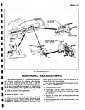
GENERAL C The brakes used fig 5 1 on both front and rear of all models are the Duo Servo single anchor type which utilize the momentum of the vehicle to assist in the brake application This self energizing or self actuating force is applied to both brake shoes at each wheel in both forward or reverse motion The brake shoe facings are bonded to the shoes and have a total area of 120 square inches The cast iron brake drums have a contact area of 9 in diameter by 13 4 in width 14 1 2 13 3 4 12 s a Y r 10 6 7 8 Fig 5 1 Duo Servo Brakes 1 Flange Plate 8 Adjusting Screw 2 Shoe Guide Plate 9 Adjusting Screw Socket 3 Secondary Shoe 10 Shoe Hold Down Assembly 4 Wheel Cylinder 11 Primary Shoe Return Spring 5 Secondary Shoe Return Spring 12 Wheel Cylinder Push Rod 6 Adjusting Screw Spring 13 Primary Shoe 7 Adjusting Screw Nut 14 Anchor Pin Wheel cylinders fig 5 2 are the double piston type permitting even distribution of pressure to each brake shoe To keep out dust and moisture both ends of each wheel cylinder are sealed with a rubber boot The wheel cylinders have no adjustments The main cylinder fig 5 3 consists of a piston which receives mechanical pressure from the brake pedal and transmits it through the brake lines as hydraulic pressure to the wheel cylinders The filler cap is accessible from inside the trunk compartment The parking brake lever is located to the left of the steering column A cable type linkage directed over three pulleys and routed through the tunnel connects ESCRIPTION 1 2 3 4 5 6 r e Fig 5 2 wheel Cylinder 1 Push Rod Boot 5 Piston Cup Expander 2 Piston b Piston Cup 3 Housing 7 Fluid Inlet 4 Spring 8 Bleeder Valve this lever to an equalizer at the under body forward of the transmission Force applied at the parking brake lever is transmitted to both right and left rear brakes by means of a single actuating cable which passes through the equalizer and is connected at each end to an actuating lever within the brake assembly fig 5 4 The parking brake lever is of the single stroke ratchet type and incorporates a trigger release which is located in the lever grip For correct adjustment procedure of service and parking brakes consult Maintenance and Adjustments in this section fa 10 11 12 III I 2 3 4 5 6 7 8 9 Fig 5 3 Main Cylinder 1 Outlet 7 Secondary Cup 2 Valve Seat 8 Push Rod Boot 3 Valve 9 Push Rod 4 Spring 10 Compensating Port 5 Primary Cup 11 Fluid Inlet 6 Piston 12 Fluid Level Rib