Jeep Parts Wiki | Ford Parts Wiki
Home | Search | Browse | Marketplace | Messages | FAQ | Guest
Prev
 Next
Next
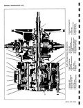
sECTI MANUAL TR CONTENTS C Corvair 500 700 and 900 Series Three Speed Transmission Four Speed Transmission Corvair 95 and Greenbrier 1200 Series Three Speed Transmission Four Speed Transmission CORVA R 500 r 71 THREE SPEED n Page General Description 6D 1 Maintenance and Adjustments 6D 3 Lubrication 6D 3 Shift Linkage Adjustment 6D 3 Service Operations 6D 3 Service Reference Guide 6D 3 Service Operations Transmission in Vehicle 6D 3 Gearshift Lever Assembly 6D 3 Shift Control Rod 6D 4 Transmission Removal and Installation 6D 5 Service Operations Power Train Removed from Vehicle 6D b Disassembly of Transmission 6D 5 GENERAL The following major changes are incorporated in the 1961 Corvair three speed transmission Transmission case now cast alloy iron Gear ratios revised for greater torque multiplica tion Mainshaft lengthened for improved durability Transmission case redesigned to incorporate concen tricity pilot in rear face In essence the Corvair manual three speed transmission is a conventional synchromesh type except for the use of concentric input and output shafts and itr mounting on the differential carrier fig 6D 1 Because of its attachment to the differential carrier the main shaft is hollow to permit passage of the clutck shaft to the front of the transmission to the clutch gear The clutch gear drives a counter gear and the remain ing power flow sequence is identical to the conven tional three speed transmission Gear ratios are 3 50 1 in first 1 99 1 in second ant 1 1 in third Reverse ratio is 3 97 1 The increased mu1 tiplication in first and second offsets the reduced res r ION 6D ANsMISS10N5 IF THIS SECTION Page 6D 1 6D 15 6D 27 6D 27 00 AND 900 SERIES TRANSMISSION MEX Page Inspection and Repair 6D 7 Bearings 6D 7 Transmission Case 6D 7 Gears 6D 7 Reverse Idler Gear Bushings 6b 7 Countergear Needle Bearings 6D 7 Clutch Gear Bearing Replacement 6D 7 Clutch Sleeve Synchronizer Rings 6D 8 Synchronizer Energizing Springs 6D 10 Assembly of Transmission 6D 10 Troubles and Remedies 6D 13 Specifications 6D 14 DESCRIPTION axle ratio of 3 27 1 so that total torque multiplication transmission times rear axle remains virtually unchanged in the first two gears The shift mechanism used is basically a single shift rod system From the transmission the single shift rod is connected by a rubber sleeve coupling to the main shift rod which is mounted in the tunnel by two nylon bushed brackets A 90 degree ball socket is integral to the front of the tunnel shaft which receives the ballend of the gearshift lever which is floor mounted in the passenger compartment By this arrangement the shift rod can be moved both fore and aft and laterally In the transmission the shift rod carries a finger which extends upward to engage either the first and reverse fork or the second and third fork depending on shift lever position As the two forks are parallel to each other a slight rotational motion of the shift rod places the actuating finger in the proper fork and permits the desired shift An interlock between the two fork shafts holds the fork not being actuated in the r neutral cross over position w MANUAL