Jeep Parts Wiki | Ford Parts Wiki
Home | Search | Browse | Marketplace | Messages | FAQ | Guest
Prev
 Next
Next
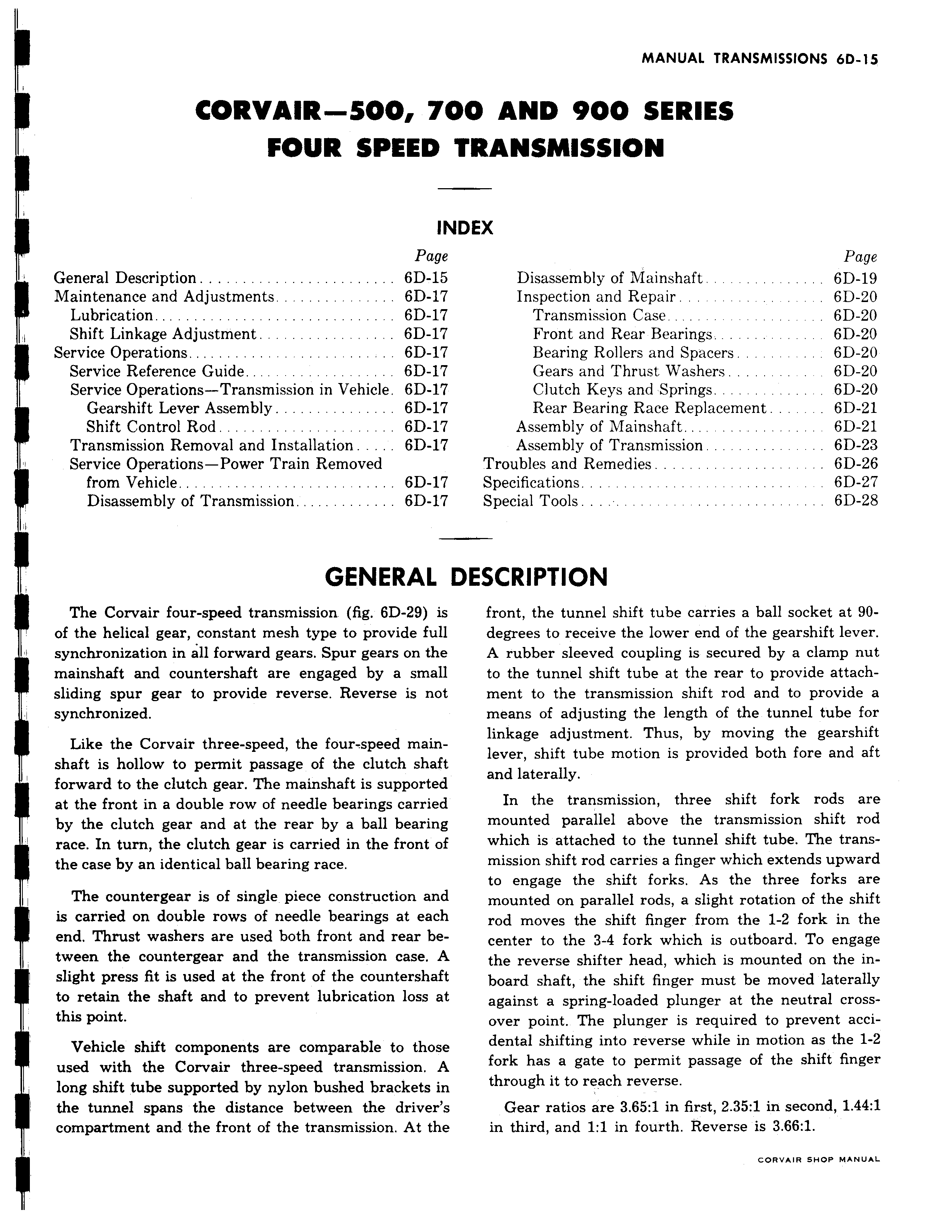
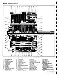
CORVAIR 500 74 FOUR SPEED m Page General Description 6D 15 Maintenance and Adjustments 6D 17 Lubrication 6D 17 i Shift Linkage Adjustment 6D 17 Service Operations 6D 17 Service Reference Guide 6D 17 Service Operations Transmission in Vehicle 6D 17 Gearshift Lever Assembly 6D 17 Shift Control Rod 6D 17 Transmission Removal and Installation 6D 17 Service Operations Power Train Removed from Vehicle 6D 17 Disassembly of Transmission 6D 17 i GENERAL I The Corvair four speed transmission fig 6D 29 is of the helical gear constant mesh type to provide full synchronization in all forward gears Spur gears on the mainshaft and countershaft are engaged by a small sliding spur gear to provide reverse Reverse is not synchronized Like the Corvair three speed the four speed mainshaft is hollow to permit passage of the clutch shaft forward to the clutch gear The mainshaft is supported at the front in a double row of needle bearings carried by the clutch gear and at the rear by a ball bearing race In turn the clutch gear is carried in the front of the case by an identical ball bearing race The countergear is of single piece construction and is carried on double rows of needle bearings at each end Thrust washers are used both front and rear between the countergear and the transmission case A slight press fit is used at the front of the countershaft to retain the shaft and to prevent lubrication loss at this point I Vehicle shift components are comparable to those A used with the Corvair three speed transmission A long shift tube supported by nylon bushed brackets in the tunnel spans the distance between the driver s compartment and the front of the transmission At the r 110 AND 900 SERIES TRANSMISSION IDEX Page Disassembly of Mainshaft 6D 19 Inspection and Repair 6D 20 Transmission Case 6D 20 Front and Rear Bearings 6D 20 Bearing Rollers and Spacers 6D 20 Gears and Thrust Washers 6D 20 Clutch Keys and Springs 6D 20 Rear Bearing Race Replacement 6D 21 Assembly of Mainshaft 6D 21 Assembly of Transmission 6D 23 Troubles and Remedies 6D 26 Specifications 6D 27 Special Tools 6D 28 DESCRIPTION front the tunnel shift tube carries a ball socket at 90degrees to receive the lower end of the gearshift lever A rubber sleeved coupling is secured by a clamp nut to the tunnel shift tube at the rear to provide attachment to the transmission shift rod and to provide a means of adjusting the length of the tunnel tube for linkage adjustment Thus by moving the gearshift lever shift tube motion is provided both fore and aft and laterally In the transmission three shift fork rods are mounted parallel above the transmission shift rod which is attached to the tunnel shift tube The transmission shift rod carries a finger which extends upward to engage the shift forks As the three forks are mounted on parallel rods a slight rotation of the shift rod moves the shift finger from the 1 2 fork in the center to the 3 4 fork which is outboard To engage the reverse shifter head which is mounted on the inboard shaft the shift finger must be moved laterally against a spring loaded plunger at the neutral crossover point The plunger is required to prevent accidental shifting into reverse while in motion as the 1 2 fork has a gate to permit passage of the shift finger through it to reach reverse Gear ratios are 3 65 1 in first 2 35 1 in second 1 44 1 in third and 1 1 in fourth Reverse is 3 66 1 cORVeIR SHOP MANUAL