Jeep Parts Wiki | Ford Parts Wiki
Home | Search | Browse
Prev
 Next
Next
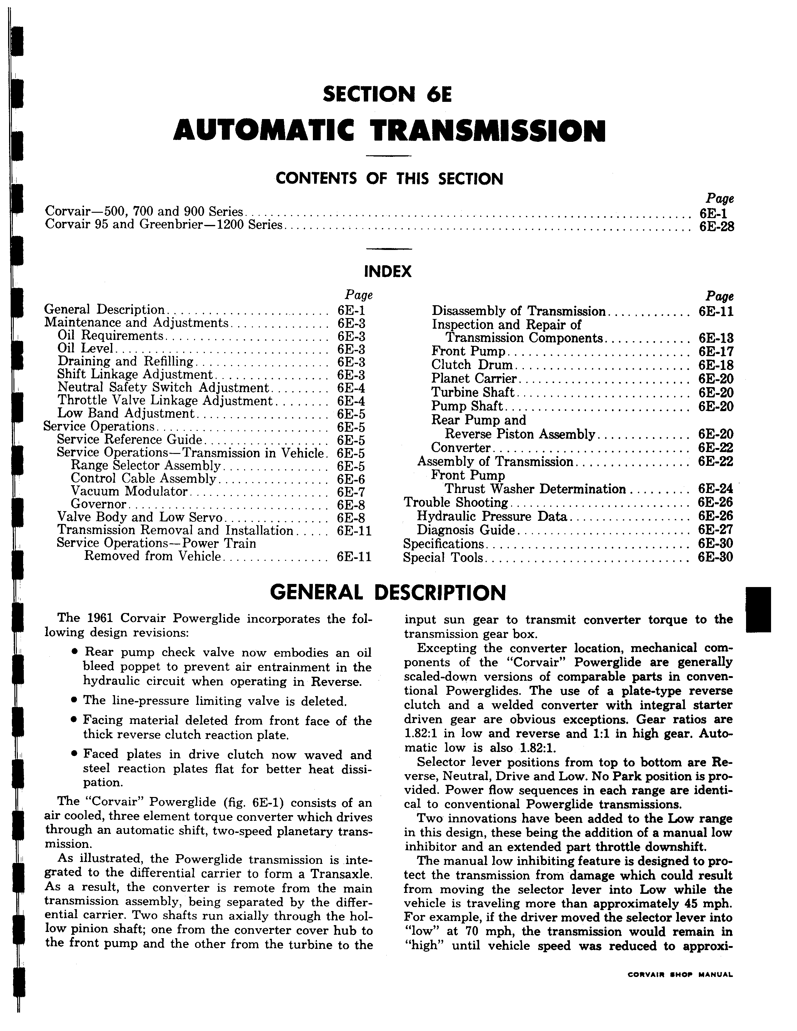
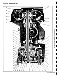
SECTI AUTOMATIC 1 CONTENTS O Corvair 500 00 and 900 Series Corvair 95 and Greenbrier 1200 Series IN Page General Description 6E 1 Maintenance and Adjustments 6E 3 Oil Requirements 6E 3 Oil Level 6E 3 Draining and Refilling 6E 3 Shift Linkage Adjustment 6E 3 Neutral Safety Switch Adjustment 6E 4 Throttle Valve Linkage Adjustment 6E 4 Low Band Adjustment 6E 5 Service Operations 6E 5 Service Reference Guide 6E 5 Service Operations Transmission in Vehicle 6E 5 Range Selector Assembly 6E 5 Control Cable Assembly 6E 6 Vacuum Modulator 6E 7 Governor 6E 8 Valve Body and Low Servo 6E 8 Transmission Removal and Installation 6E 11 Service Operations Power Train Removed from Vehicle 6E 11 GENERAL I The 1961 Corvair Powerglide incorporates the following design revisions Rear pump check valve now embodies an oil bleed poppet to prevent air entrainment in the hydraulic circuit when operating in Reverse 0 The line pressure limiting valve is deleted e Facing material deleted from front face of the thick reverse clutch reaction plate 0 Faced plates in drive clutch now waved and I steel reaction plates flat for better heat dissipation The Corvair Powerglide fig 6E 1 consists of an air cooled three element torque converter which drives through an automatic shift two speed planetary transmission As illustrated the Powerglide transmission is integrated to the differential carrier to form a Transaxle As a result the converter is remote from the main transmission assembly being separated by the differential carrier Two shafts run axially through the hollow pinion shaft one from the converter cover hub to the front pump and the other from the turbine to the ON 6E VANSMISSION F THIS SECTION Page 6E 1 6E 28 DEX Page Disassembly of Transmission 6E 11 Inspection and Repair of Transmission Components 6E 13 Front Pump 6E 17 Clutch Drum 6E 18 Planet Carrier 6E 20 Turbine Shaft 6E 20 Pump Shaft 6E 20 Rear Pump and Reverse Piston Assembly 6E 20 Converter 6E 22 Assembly of Transmission 6E 22 Front Pump Thrust Washer Determination 6E 24 Trouble Shooting 6E 26 Hydraulic Pressure Data 6E 26 Diagnosis Guide 6E 27 Specifications 6E 30 Special Tools 6E 30 ASCRIPTION input sun gear to transmit converter torque to the transmission gear box Excepting the converter location mechanical components of the Corvair Powerglide are generally scaled down versions of comparable parts in conventional Powerglides The use of a plate type reverse clutch and a welded converter with integral starter driven gear are obvious exceptions Gear ratios are 1 82 1 in low and reverse and 1 1 in high gear Automatic low is also 1 82 1 Selector lever positions from top to bottom are Reverse Neutral Drive and Low No Park position is provided Power flow sequences in each range are identical to conventional Powerglide transmissions Two innovations have been added to the Low range in this design these being the addition of a manual low inhibitor and an extended part throttle downshift The manual low inhibiting feature is designed to protect the transmission from damage which could result from moving the selector lever into Low while the vehicle is traveling more than approximately 45 mph For example if the driver moved the selector lever into low at 70 mph the transmission would remain in high until vehicle speed was reduced to approxi